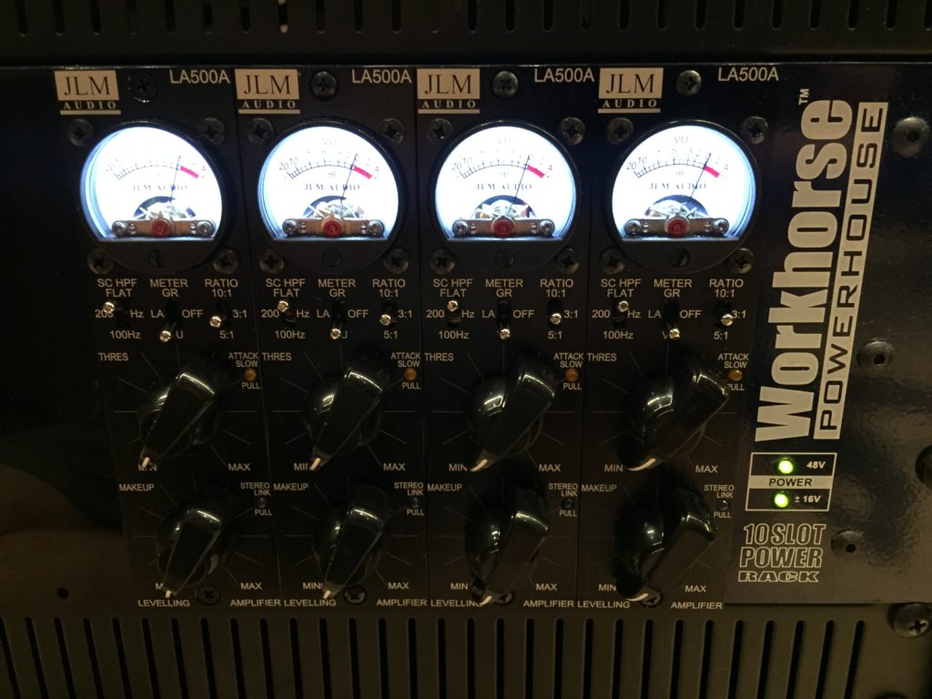
Our summer-long build-out of the studio’s 500-series racks continues. This week I’m working on adding four new LA500A units from Australia’s JLM Audio.
Just like with preamps, the goal of doing all this building (aside from the fact that it’s fun and saves a lot money over buying manufactured stuff) is to make sure that we have a lot of different styles and flavors of compressors available to us when recording or mixing. Typically I’ll build one unit of a particular model that I’m interested in, and if the build quality is good, and, probably most importantly, the unit SOUNDS good, I’ll order one to three more, depending on how we’re planning to use them in our day to day recording projects. It’s key for us to be able to record a fully miked drum kit at our studio, for example, which can easily involve 12 or more mics and a compressor channel for each. And it doesn’t make sense to have different compressors on each channel of a pair of stereo overhead mics, or on, say, four different tom drums, which all need to sound like they relate to each other sonically. So I’m particularly interested in units (like the LA500A, or the FET/500’s I built last month) that can be linked for stereo operation when the need arises.
The LA500A was developed by Joe Malone of JLM Audio, an Australian company that offers a wide variety of DIY kits for various pieces of studio gear. Like the FET/500, which is based on the legendary 1176LN Peak Limiter, the LA500A seeks to recapture the sound of a pair of equally legendary compressors, the Teletronix LA2A and LA3A.
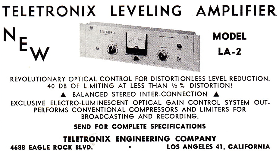
The LA2A “Leveling Amplifier”, as compressors also used to be called, was invented in the early 1960s by James F. Lawrence. The original units were made until 1969, but the line was resurrected by Universal Audio in 1999 and new production units are still available today. And just like the 1176, the reissued LA2A unit has now been in production longer than the original unit was. What goes around comes around.
[blockquote blockquote_style=”boxed” align=”left” text_align=”right” cite=”” style=””]The original LA2A units were made for only a few years, from the early 60s until 1969. The reissued units have now been in continuous production since 1999.[/blockquote]
Mr. Lawrence had a background in electrical engineering, and served as a radar operator during World War II. He also worked for a time at Jet Propulsion Labs (JPL), developing optical sensors for the Titan Missile Program. But his real passion was radio. While working at a Los Angeles area radio station in the 1950s, he became frustrated with constantly having to manually adjust the volume level going to the station’s transmitter.
Drawing on his experience at JPL, Mr. Lawrence developed a circuit that used an electroluminescent (EL) panel, not all that different from those green glowy ones found in your night light, to control the amount of gain reduction applied by the unit.
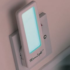
This circuit seems so charming in a 1950’s sort of way: use the strength of an incoming audio signal to control the brightness of a small EL lamp. Then, place a photo sensor in front of the panel, and turn down the output signal (that is, apply gain reduction) on the basis of how much light is reaching the photo sensor. Insert a couple of control knobs in the circuit to control how much input signal reaches the EL panel, and how much gain reduction is applied by the photo sensor, and you have the basic idea of how these units work.
[blockquote blockquote_style=”boxed” align=”left” text_align=”Left” cite=”” style=””]The LA2A’s opto compression circuit seems so charming, in a 1950’s sort of way.[/blockquote]
Opto-based compressors such as the LA2A and LA3A have a characteristically slow response. If you’ve ever turned off an EL panel and noticed how it continues glowing for a few seconds, you get the idea. That means these units weren’t as useful for “peak reduction” situations where the compressor had to be fast enough to catch the attack transients (the peaks) of the signal as they were passing through the circuit. But a slower attack time is useful in situations where the audio material would benefit from having the “tails” of the notes lengthened or made more prominent — think a drum kit where you’re trying to accentuate the ring of the drums rather than the initial sound of the stick hitting the skin. The LA2A circuit is relatively slow if you’re trying to knock down an instrument’s attack, but great for boosting the sustain of the instrument so that it sounds rounder and, well, huge-er.
The LA2A featured vacuum tubes, known for their warmth and, er, pleasantly nonlinear character (aka distortion). The later LA3A unit, while also an opto-compressor, was solid state. So the response of their compression circuitry was similar, even if the sound of these units was somewhat different.
So that’s a little bit of history. Turning to the current project, the LA500A is JLM’s take on the LA2A/LA3A design, in a very compact little unit.
Since the unit is solid state, I suppose it’s more like an LA3A in that respect. Also, the JLM units use an LED in place of an EL panel. Since LEDs can switch on and off much more quickly than an EL panel, the response of the gain reduction circuit in the LA500A is actually faster than the vintage units they seek to emulate. JLM’s earlier version of these compressors (called simply the LA500) didn’t account for this difference. But the company later added a “slow” setting that gives you more of the old-school slow response time the LA2A/LA3A was known for. The newer units also add a stereo linking function, which lets you tie the gain reduction circuitry between two adjacent units together so that you can use them as a pair on stereo sources.
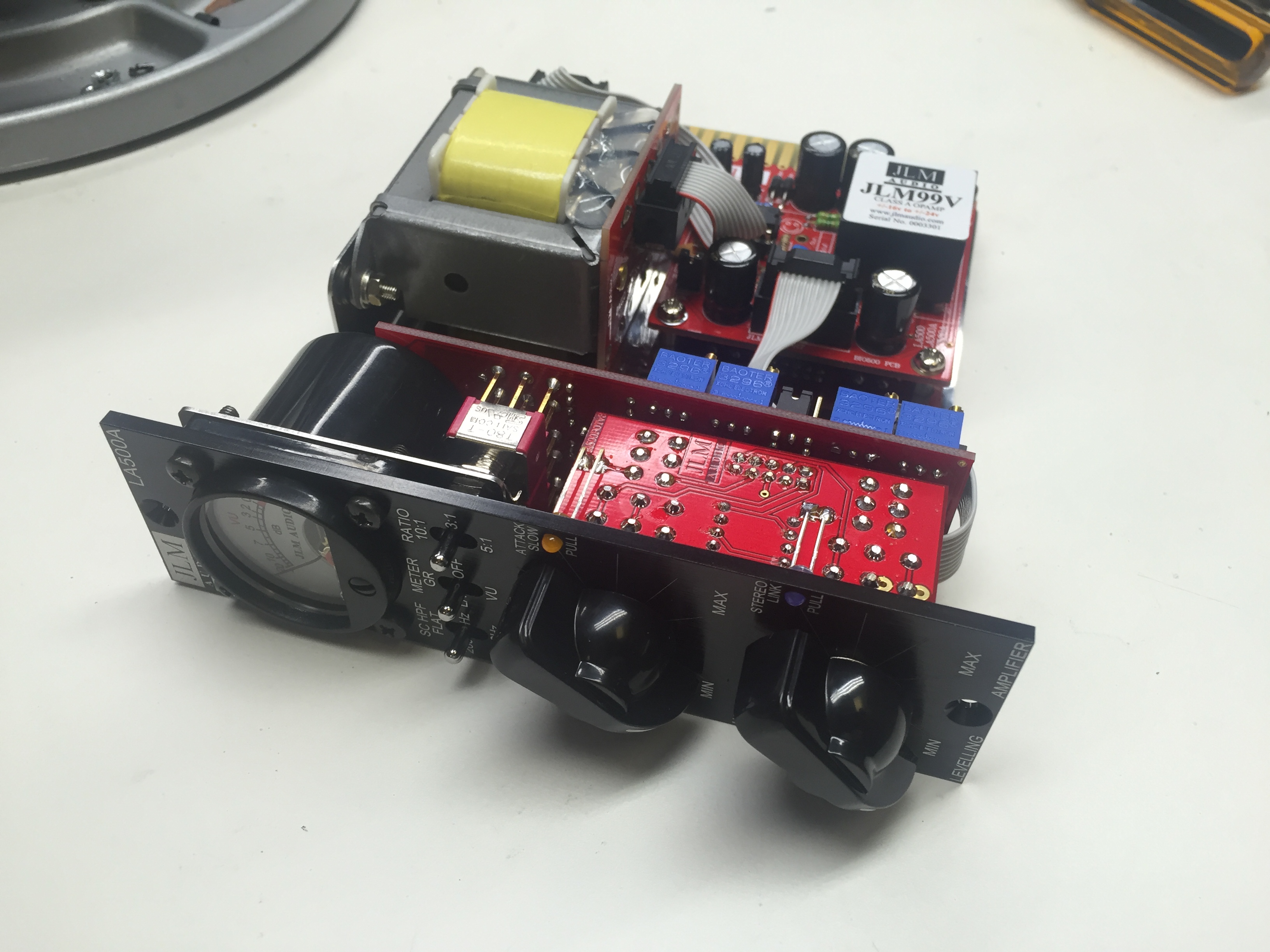
JLM’s kits are well regarded in the builder community, so I figured I’d pick one up and see what all the fuss was about. Wow. These units are an absolute joy to build. They are extremely well laid out. The circuitry is divided into three small PC boards, which are connected to each other with a couple of low-profile ribbon cables.
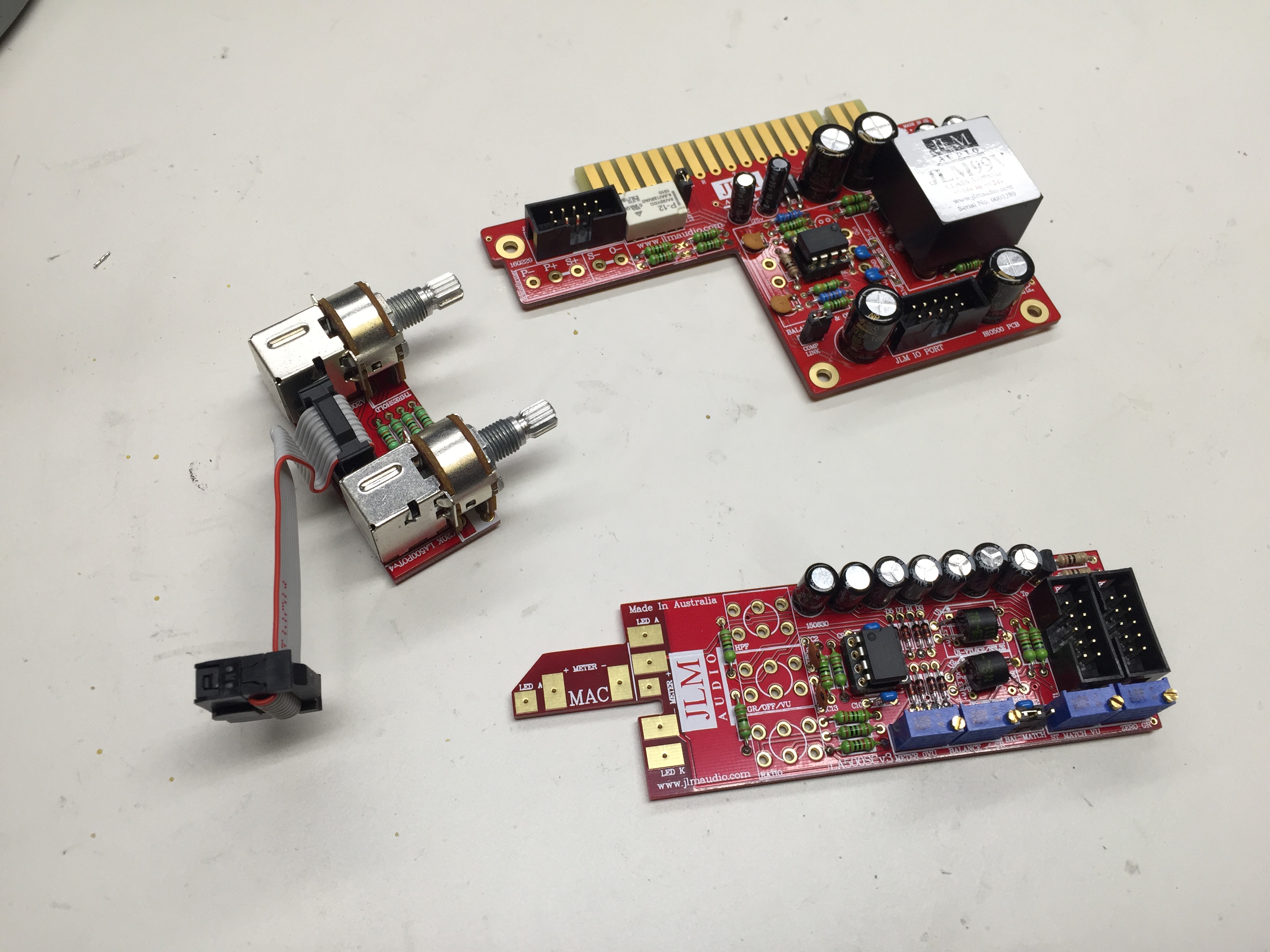
The parts for each board are packaged separately, so it’s really easy to divide and conquer as you’re building; there just aren’t that many parts that need to be looked after as you’re working on each board. Another big plus is the fact that JLM has silk screened the component values onto the boards themselves. In a lot of kits, you get a part number, such as “R40”, “C12” and “D3”, for “Resistor 40”, “Capacitor 12,” and “Diode 3″. Using that information, you usually have to go through an accompanying printout that lists all the values for each component, find that part, and make sure you’re matching the, say, 110 ohm resistor to the opening marked R40.
[blockquote blockquote_style=”boxed” align=”left” text_align=”right” cite=”” style=””]JLM’s DIY kits are an absolute joy to build. They are extremely well laid out and easy to assemble.[/blockquote]
In JLM’s kits, though, the board not only says “R40” but also that the part that goes there is 110 ohms. So the build time is greatly reduced. It’s easier to find the part you’re looking for, and at least a little easier to verify that the correct component is going into the correct spot on the board.
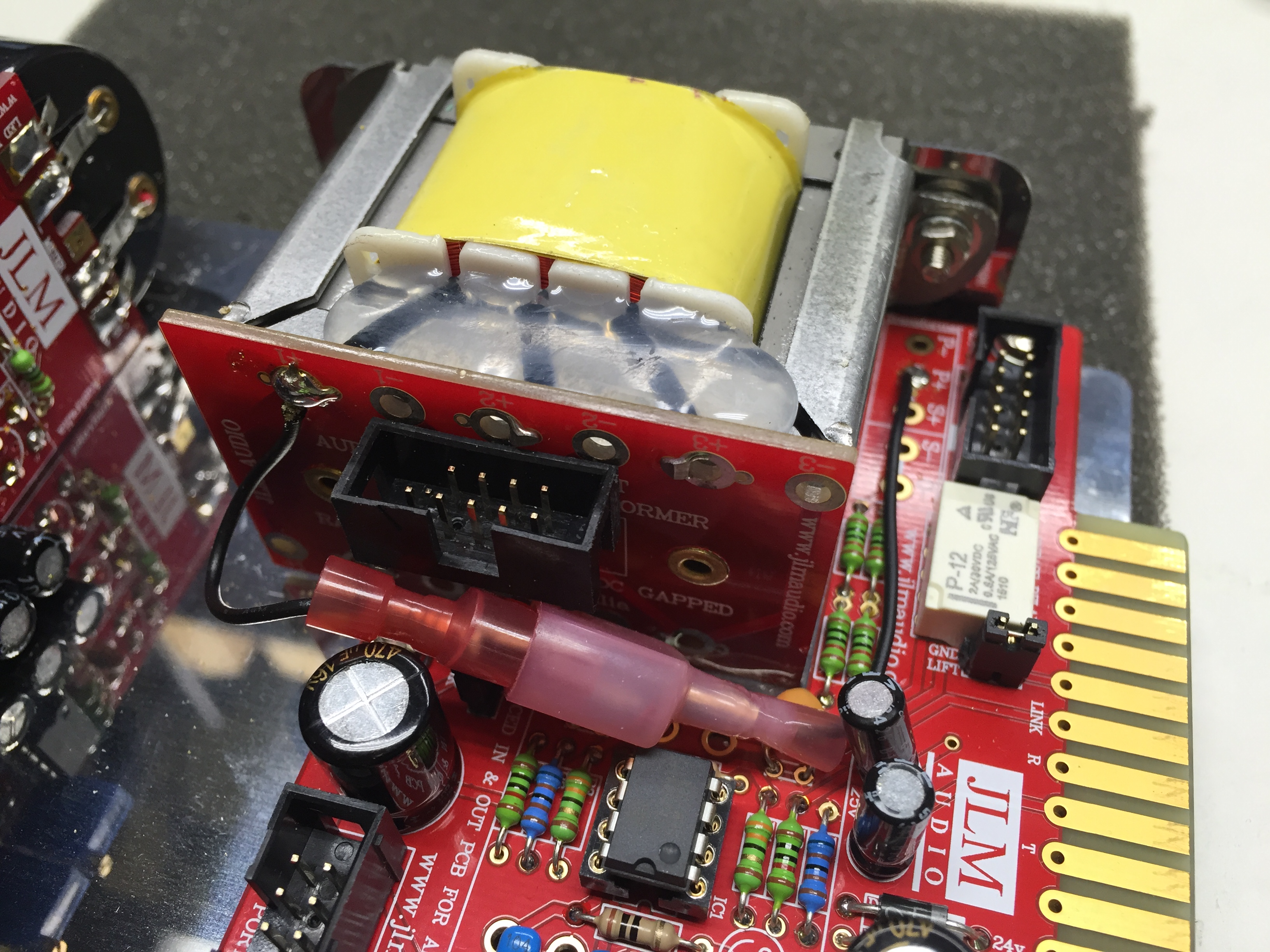
My other favorite thing about the JLM units is that the transformers arrive from the factory with a ribbon cable connector already attached. Transformers usually arrive with a long, unruly set of colored wires, and it falls on the builder to carefully trim and install somewhere between 8-10 wires without mixing up the colors or melting the insulation. I remember one build guide warning that the transformer wires were “not like hair, and won’t grow back if you over-trim them”, because it’s easy to get a little too aggressive with the snips and wind up making more work for yourself trying to add length back after you’ve cut a lead too short. In the case of JLM, the transformers are an absolute snap to install. Tighten a couple of screws, connect the ribbon cable, and you’re ready to rock.
I did have two problems building my first unit. First of all, when I connected the unit and went through JLM’s testing process, I couldn’t get any sound to go through the unit. The meter was moving and the unit was acting like it was getting audio, but nothing was getting through to the output. With the help of Joe Malone, we traced the problem back to a particular connection coming off the unit’s transformer. It turned out that one of the pins in the transformer’s ribbon connector wasn’t manufactured correctly, and it wasn’t making a hard connection with its mating connector.
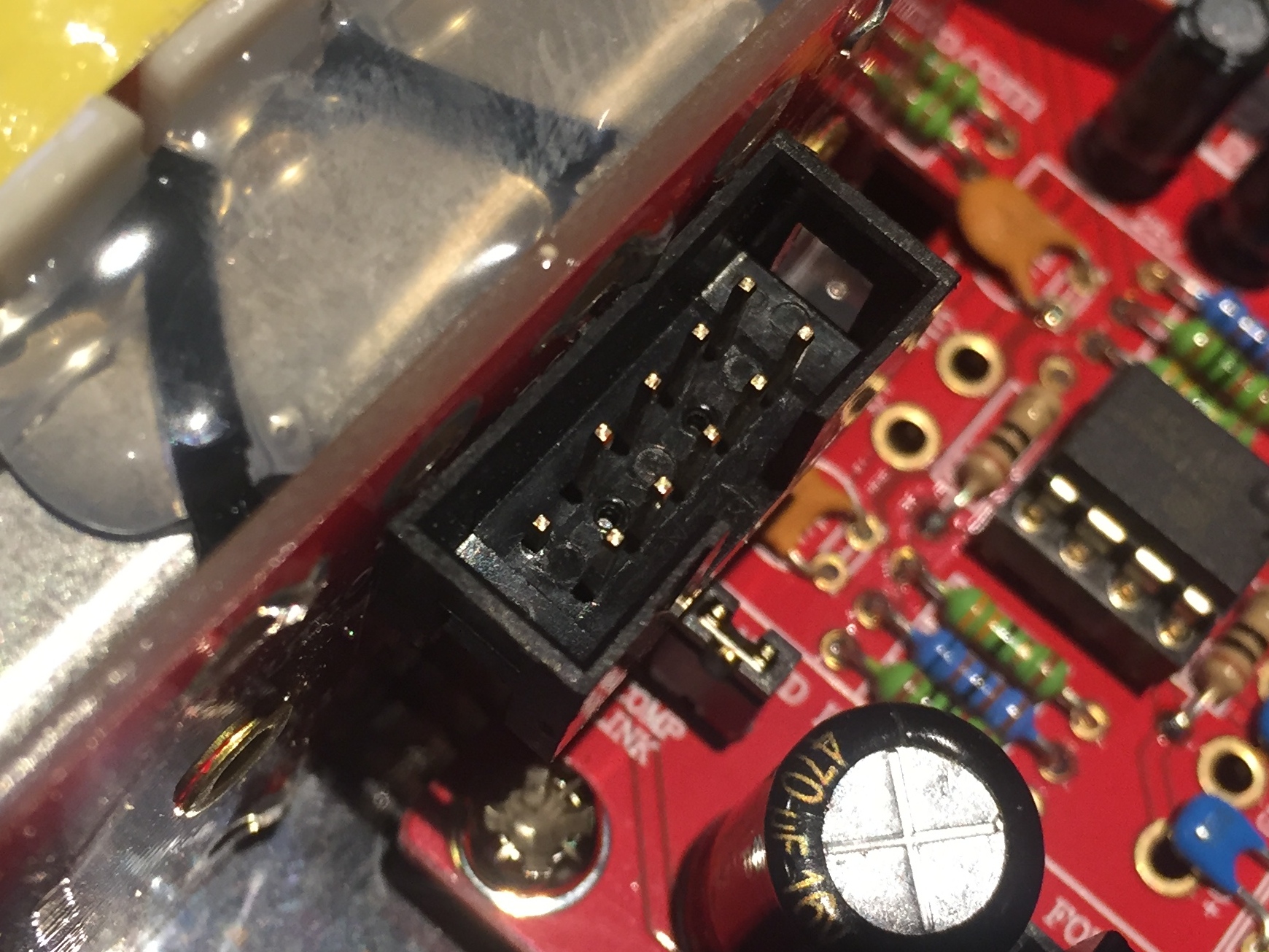
Joe told me to bypass the problem by simply soldering a wire between the affected output line on the transformer, and the spot on the main circuit board where the signal was supposed to go. Now, it’s unlikely that I’d ever need to disassemble one of these units, but since the rest of the connections from the transformer go through an easily-removable ribbon connector, it seemed silly to tie one lead from the transformer to the board with solder while the rest could simply snap out. It felt a little like tying one shoe with a bunny-ear loop, and the other with a quadruple knot. So I included a detachable connector to the bypass line, just in case.
Plug the hotwired unit back into the rack, run some audio through the line, and — bingo — problem solved.
The other thing I found a little tricky with the LA500A — and this is a minor quibble — is the setup process after the build is complete. The meter calibration for these units is VERY tricky and time consuming. It involves a lot of switching back and forth between two modes on the panel of the unit, while using a tweaker screwdriver on a small potentiometer on the main circuit board, until you get the same gain reduction reading on the meter in both modes.
Once these units are assembled, though, they sound GREAT. The way the slow opto-compressor attack brings out the sustain on a drum kit? Amazing. Once I had one of these units built, I knew I would be building more. I have now finished four of them, and I look forward to using them on all sorts of sources, especially drums.