“47.” “414.” “1073.” In pro audio circles, there are a lot of pieces of gear that have become so famous, so well known, or so ubiquitous, that you simply need to mention the model number and everyone knows what you’re talking about. This is the story of another such number: 1176.
Compressors are widely used in audio production to keep the dynamic range of a signal under control: in essence, to “compress” the difference between the loudest and softest parts of a signal by rapidly adjusting the level (or gain) of the signal in response to a predetermined formula. When the signal goes above a particular threshold volume, the compressor turns down the level on the signal by a certain amount before returning the signal back to normal when the signal drops below the threshold level. They’re particularly useful when recording singers who cover a lot of range from loud to soft, as well as for taming particularly percussive sounds such as brass horns or drums, where the transient (or peak) of the instrument is particularly loud and can risk clipping the audio signal. Compressors can also bring up subtle details, so that a singer’s slightest whisper can be heard alongside her loudest wail.
Compressors also have a long history in radio production, where they help even out differences in volume between different songs, and ensure that the broadcaster is getting absolutely as much signal to the transmitter as possible. That way, even if you’re listening on a tiny transistor radio, you’d still be able to hear the song. In that respect, compression is, historically, the “sound of radio.” Over the years, compressors have become a creative tool too — certain models of compressor are favored for the audio “flavor” they impart to the signal as it passes through the unit’s circuitry.
In 1968, UREI introduced the 1176 Peak Limiter, the first all solid-state compressor. It used a field effect transistor (FET) to provide the gain reduction, unlike earlier designs that used a vacuum tube or an opto-based circuit.
The biggest difference in the operation of the 1176 as compared to its tube-based predecessors was speed: a compressor’s job is to detect changes in the incoming signal, and react by turning down the gain before the signal passes to the output. Too slow, and the initial peak of the signal (the crack of the drumstick on the drum head, for example) passes through the compressor’s circuitry before it can react. Sometimes you want to do this on purpose, but more often than not the compressor’s job is to tame the louder, initial transients of the signal. Hence the name: the 1176 Peak Limiter.
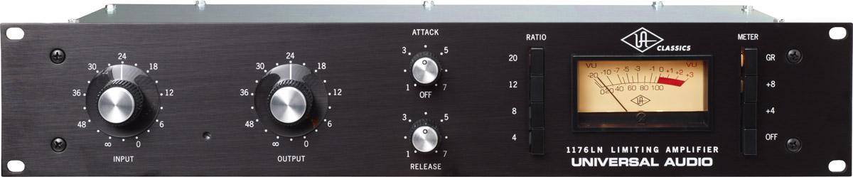
With its lightning quick reaction time — the 1176’s fastest attack time setting is 20 microseconds — the unit quickly developed a reputation as a lion tamer on drums. But engineers also loved the flavor imparted on the signal by the 1176’s circuitry. It’s no wonder that vintage units from the late 60s are still prized today, and that the successor to the company that originally made the unit — Universal Audio — put the most famous version of the 1176, the Revision D “blackface”, back into production in 2000 (it’s also funny to think that the updated unit has now been in production longer than the original units were).
In their original shape, the 1176’s take up two rack units (RUs) each. We’re going to need a bunch of them for recording drums, though, so it’d be tough to accommodate that in our racks. Universal Audio’s reissue of the 1176LN runs $2000. Ouch. So I started looking for ways to save both money and space, while still getting the classic sound of the 1176’s FET-based compression. That’s where Hairball Audio and Mako Natsume (aka MNATS) come in. Hairball offers a DIY kit version of the 1176, in 500 Series format, for just $425. Perfect. I can build four of these units for less than the cost of one of the original-sized 1176s.
Today, I finished the first one.
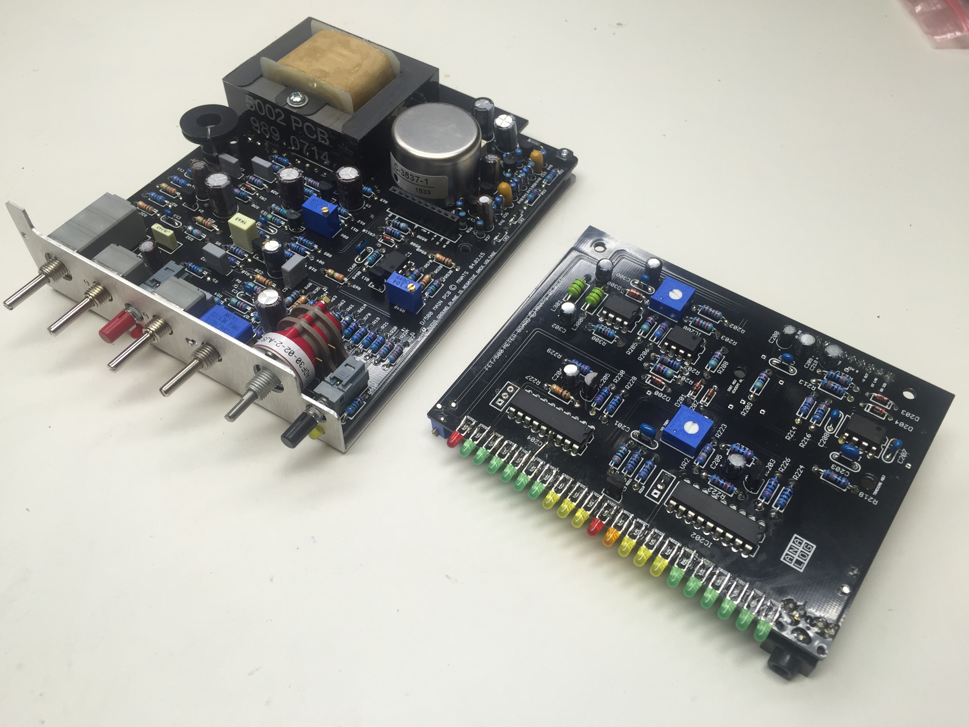
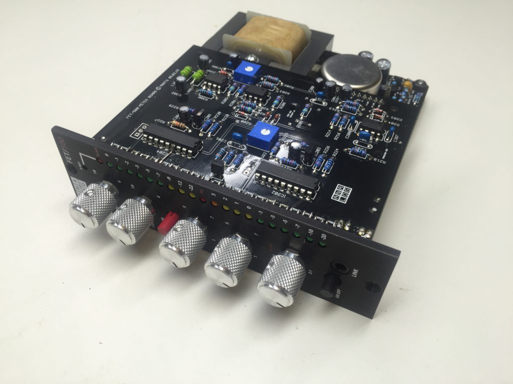
The unit has two boards, a main PC board and a separate meter board that connects to the main PC via a 10-pin connector. There’s not a ton of parts, and the layout isn’t particularly difficult until you get to the LEDs for the meter, where things get a little tricky.
There’s a saying in the kitchen that the first pancake in the batch always comes out a little weird (Ann and I got a good laugh from a mom we met who referred to her first child, who was a little weird, as her “first pancake”). I’m not sure why this is — maybe you overcorrect because you’re not sure how hot the griddle is, or you’re not sure how much batter to use per pancake. Whatever the reason, after that first one, the rest usually come out much rounder and more evenly cooked. This first FET/500 unit is definitely a “first pancake.”
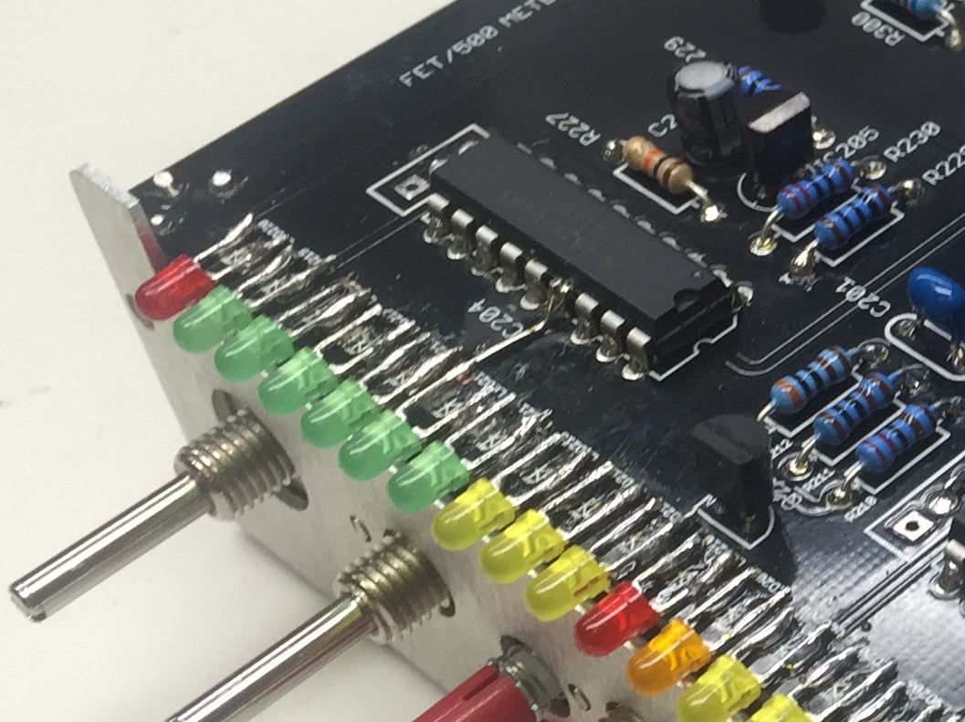
The tricky part of these units is the way the LEDs for the meter are installed on the board. They are all attached as “surface mount” devices. In traditional “through-hole” soldering, the component sits on top of the board but is held in place by a couple beads of solder applied to the component’s leads on the bottom side of the board. With surface mount soldering, on the other hand, there’s no holes involved; the only thing holding the part in place is a small joint of hardened solder on the top side of the board. Machines have no trouble doing this sort of work, but it’s tricky for a human because you need to heat both the part and the solder joint, at the same time, without moving the part. Once the solder joint cools, it’s perfectly set, but until then, it can still wiggle around on you and create a huge mess.
Hairball Audio suggests using a “jig” approach to this part of the project, where you stick a couple of LEDs to be soldered into the faceplate of the unit, then hold them temporarily in place with masking tape while you solder them. It took me a little while to get the hang of that, but it got a little easier after a while. Still, this being my “first pancake,” it’s a little rough around the edges. I overheated one of the LED solder pads, which destroyed it, so I had to bypass it. I simply soldered the LED’s lead directly to the leg of the IC chip that drives it.
With that little band-aid soldered firmly in place, I hooked the unit up to our rack and tested it out. It works perfectly! And of course, the meter is really just esoteric. The unit SOUNDS great as well, and that’s why I enjoy building these things. Probably the most interesting thing about this unit as compared to a classic 1176 is the digital meter. The original 1176s have an analog meter, which is simply not fast enough to realistically demonstrate how fast a FET-based compressor really is.
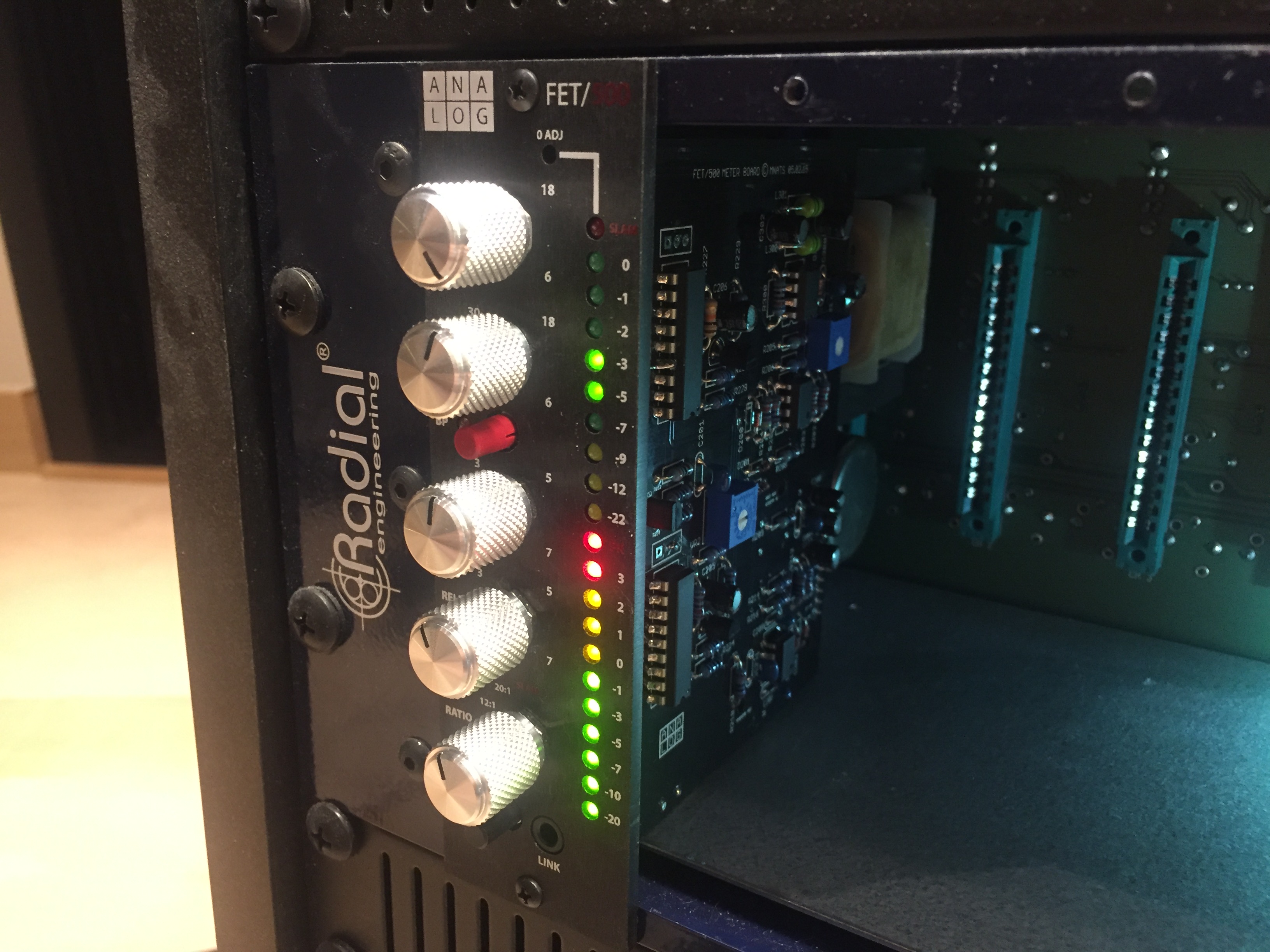
So while there’s something cool and vintage-y about having an analog meter, for these compressors, I will happily take the digital equivalent. It’s MUCH easier to dial in the attack settings on these units, because you can see right away how the compression circuitry is keeping up with the signal coming into the unit. I’ve got three more of these kits lined up on my workbench, so the plan is to have four of these. I expect the builds to go a lot more smoothly, as the “second pancake” often does. An 1176 is great on all sorts of studio duty, so we look forward to getting a lot of mileage out of these.